How Does a Long Steel Bar Feed into a CNC Lathe?
Table of Contents
A bright steel bar feeder advances fresh stock after each part is cut off; the lathe grips and machines the exposed end.
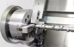
A long bright steel bar can become many small parts because a bar feeder pushes fresh material into a lathe after each finished piece is cut off. The lathe grips and rotates the bar while cutting tools shape the exposed end. Then the next short section moves forward and the cycle begins again. Much of the original bar can remain hidden behind the machine while the visible end steadily turns into parts.
A CNC lathe is a computer-controlled turning machine. “Turning” means removing material from a rotating workpiece with a cutting tool. A bar feeder is its material-delivery partner, rather like a magazine that supplies the next length of raw material instead of the next sheet of paper.
Follow one piece of steel
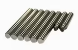
Imagine a machine making a row of small cylindrical spacers. A spacer is simply a short piece that keeps other components a certain distance apart. The material starts as one long rod, not as a pile of already separated little cylinders.
The front of the rod projects into the lathe’s working area. A gripping device, such as a chuck or collet, holds it. The spindle is the rotating assembly that carries this gripping device and turns the workpiece. A tool moves along the exposed steel, removing material as chips. Other tools may shape the end or create a hole, depending on the part.
Once this little section has its intended form, a narrow cutting tool separates it from the parent bar. The feeder then advances another section. The machine does not need a new long rod for every spacer; it repeatedly works on the leading end of the same rod.
Actual machine arrangements differ, but this sequence explains the central idea: grip, machine, separate, advance. The apparently simple finished object is one slice of a much longer production journey.
The feeder supplies material; the lathe creates the shape
The two machines are often shown as one automated arrangement, but their jobs are different. The feeder manages the movement of the long stock toward the cutting area. The lathe controls the rotation and tool movements that establish the part’s geometry. A computer program coordinates these actions so the next section appears at the appropriate stage of the cycle.
CNC stands for computer numerical control. It describes how commanded positions and operations are controlled. It does not mean that the material can move freely while every other part of the machine continues unchanged. Cutting, gripping, and feeding must be coordinated because each step changes what is holding the steel and where the cutting tools can act.
Picture the spacer-making cycle as a handoff. During cutting, the bar must be held securely in the intended position. During advancement, the arrangement must allow the stock to move forward. After movement, it must again provide the grip needed for the next machining stage. The feeder does not simply push harder against a permanently locked bar.
This explains a pause visible in many machining videos. When the tool moves away and a short fresh length appears, the machine is changing the relationship between stock, gripper, and cutting area. To a viewer the action is brief, but it separates one part from the next.
A bar feeder is also different from a robot that picks up an already cut blank. The feeder moves continuous stock through the machine’s passage. A blank-handling robot transfers separate objects. Both can automate material supply, but they create different starting conditions for the machining cycle.
The support system you do not see
A long bar cannot be understood only by watching its tip. The material farther back also needs support. Depending on the equipment, guide channels and spindle liners help control the bar as it moves and rotates. A spindle liner is a sleeve inside the spindle opening that reduces the space around the bar.
Think of turning a long pencil inside a much wider tube. With a generous gap, the pencil has more room to move sideways. A closer supporting sleeve changes that behavior. The analogy explains the purpose of support, though industrial machines have their own designs and operating limits.
Haas describes bar straightness, bar-end preparation, and the relationship between stock and spindle support in its bar-feeder operation guide. These details matter because feeding is a physical journey through connected spaces, not simply a command telling the bar to move forward.
Why a long rotating rod needs more than an end grip
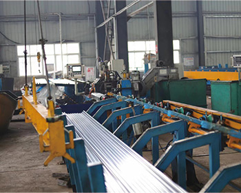
A short length held close to the cutting area and a long unsupported rod are mechanically different objects. The longer one has more opportunity to flex, and any departure from a straight, centered shape can create movement as it rotates. Support changes how much of the bar is free to move and where its motion is restrained.
Imagine holding a ruler near its end, then holding it with a second hand much closer to the point you are pressing. The material has not changed, but the shorter free span is harder to bend visibly. Bar-support systems use this same broad geometric principle within their particular machine designs.
Roundness and straightness describe separate features. A rod can have a circular cross-section at every location while its centerline forms a gentle bow. It can also follow a straight centerline while its section is slightly oval. The first affects the path the center follows; the second changes the local outside shape presented to a guide or gripper.
The bar end has its own role. The leading end must enter successive openings, while the trailing end interacts with the feeding arrangement. A projecting burr or uneven end is a local feature, quite different from a bend distributed along the whole rod. All three can be hidden by the casual phrase “the diameter looks right.”
These observations explain equipment behavior without prescribing an operating speed or setup. A feeder’s permissible stock, supports, and sequence belong to its actual design and instructions. A general animation cannot establish the correct settings for a different machine.
Why the bar’s shape matters more than its shine
Bright steel bar has a metallic-looking surface produced by finishing operations that remove scale or work the surface. The word “bright” describes its appearance and product form; it does not mean that every bar is perfectly straight or identical in every dimension.
A bend changes how the bar moves through guides. Variation around its circumference changes how evenly it sits inside round supporting features. A damaged end can interfere with the first movement into another opening. These are different geometric problems, even if all the bars look equally shiny from a distance.
This is why footage of automated turning can be misleadingly effortless. The tool at the front gets the attention, but the unobtrusive material behind it must travel, rotate, and remain supported in a coordinated way.
Eventually there is too little bar left to produce another part while still holding the material as the machine requires. This unused tail is called a remnant. Some steel also leaves as chips and as the material removed during separation. One long rod therefore becomes a collection of finished pieces, a stream of chips, and a final short tail. The feeder connects those repeated cutting cycles into one continuous-looking performance.
Jiyuan’s bright steel bar range is relevant at the starting-stock stage of this journey. Its grade, size, supplied length, and condition describe the material before it becomes a finished component.
One bar becomes more than a row of finished parts
Suppose an imaginary production run begins with 1,000 mm of usable stock. Each part occupies 20 mm along the bar, and separating it uses another 2 mm of length. In this simplified model, each completed cycle consumes 22 mm. Forty cycles consume 880 mm, leaving 120 mm before allowing for any extra facing, gripping, or final remnant.
The 2 mm in that example is an illustration, not a universal parting width. Its purpose is to show why dividing bar length only by finished-part length can overstate the number of parts. Metal removed during separation is real material, even though it never appears as a finished object on the collection tray.
Material also leaves radially as the outside is turned down. A spacer with a hole loses material from its center during hole-making. The final pieces can therefore weigh much less than the original bar even when most of its usable length has passed through the machine.
Chips are the accounting evidence. They contain steel that once occupied the spaces outside the final surfaces. The remnant contains steel that was never converted into another complete part. Finished pieces, chips, and leftover stock together describe the material journey much more accurately than the piece count alone.
Following Bar Stock Through the Lathe
Does the bar feeder machine the steel into parts?
The feeder advances stock; the lathe performs the cutting. The lathe grips and rotates the bar while tools shape the exposed portion. After a part is separated, the feeding arrangement presents another length of material for the next cycle.
Why does a long bar need support behind the lathe?
An end grip does not support every part of a long rotating bar. Unsupported length can bend or move during rotation. The feeding and support arrangement controls the stock outside the cutting area, and its suitability depends on the bar and the specific machine.
For a material discussion connected to a feeding application, you can send Jiyuan the required bar diameter and length, the grade if established, and a short description of the intended part and feeding arrangement. Those details connect the material question to the physical journey described here, while machine-specific setup remains a separate matter.