How Can a Solid 1045 Steel Bar Become a Hollow Bushing?
Table of Contents
A solid 1045 bright bar becomes a hollow bushing when drilling and boring remove its center as chips, leaving a cylindrical wall.
A solid 1045 bright bar becomes a hollow bushing by having material removed from its center. A hole can be drilled and then enlarged or refined by boring, leaving a cylindrical wall around the opening. The missing middle leaves as chips. The bushing is not hollow because the solid steel somehow spread outward into a tube.
A bushing is a sleeve-like component that can guide, space, or support another part. Its particular role depends on the assembly. A grade name such as 1045 identifies the starting steel; it does not create the sleeve shape.
Begin with two circles
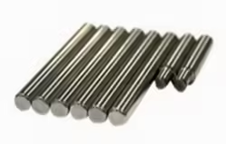
Look at the end of a round bar and draw a smaller circle inside it. The ring between those circles is the cross-section of a simple bushing. To create that ring from solid stock, the central circle’s material has to go somewhere.
A drill creates an initial hole by cutting into the solid metal. Its cutting edges remove material while the tool and workpiece rotate relative to one another. Chips travel out of the hole rather than remaining inside the intended opening.
Boring works on a hole that already exists. A cutting tool reaches inside and removes material from the internal wall, enlarging or refining it. This distinction is easy to miss because ordinary conversation often calls any hole-making operation “drilling.”
The distinction also explains why an initial hole and a finished bore need not be the same size. The first opening creates access. A subsequent internal cut can bring its diameter and surface closer to the intended result. The two operations solve related but different problems: getting into the solid center and shaping the internal cylinder.
Meanwhile, the outside may be turned to another diameter, and an end face may be machined flat. These are separate surfaces on the same object. A sleeve can have a carefully finished outside while its bore is still at an intermediate stage. Its nearly recognizable shape does not mean every surface is complete.
The grade number does not change this geometry. Calling the starting material 1045 provides material identity, while “bushing” names a part shape and role. A hollow cylinder of another material would still have an inner diameter, outer diameter, and length. The material matters to machining and service, but it does not replace those dimensions.
The inside is a less accessible surface
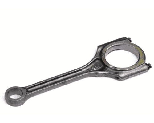
Machining an outside diameter leaves open space around the tool. Working inside a hole restricts that space. The cutting tool must reach into the opening while clearing chips and avoiding unwanted contact.
The tool’s projecting length matters because a slender support can bend and vibrate. Sandvik Coromant’s discussion of internal turning and damped tools addresses this difficulty. An internal wall may look simple in the finished part while having been harder to reach during machining.
For the reader watching the process, the important distinction is that the outer cylinder and inner cylinder are separate surfaces created through separate contacts with cutting tools.
There is an important difference between reaching a surface and reaching it rigidly. A tool that barely fits into a small bore may have little room for a thick support. Increasing its reach without changing that support can make movement under cutting forces more noticeable. The finished hole may be simple to draw while the tool arrangement needed to produce it is constrained.
Chips also need a route out. On an outside turning operation, the surroundings are comparatively open. Inside a hole, the new chip shares limited space with the tool and workpiece. If it does not leave the cutting region readily, the process can be disturbed. The empty space seen in the final bushing was a busy, restricted workspace during manufacture.
In a through-hole, an opening continues from one end to the other. A blind hole stops within the material. The distinction changes access and the shape of the end of the opening. A simple sleeve usually brings to mind a through bore, but the word “hole” alone does not tell you which geometry is being made.
Jiyuan’s bright steel bar range covers a published φ12–300 millimeter diameter family. Round starting stock naturally contains the outer cylindrical envelope from which a sleeve-like part can be machined. The useful connection is between the available starting section and the material that must remain after the bore and outside are finished.
Account for the missing steel
Take an illustrative cylindrical blank with an outside diameter of 30 millimeters. If its finished central hole is 20 millimeters across and its length is unchanged, the hole occupies 20² ÷ 30², or about 44.4 percent, of the original cylinder’s volume.
The remaining ideal sleeve contains about 55.6 percent of that volume before considering any other cuts. Those percentages come from circle geometry; they do not depend on choosing 1045 rather than another steel of the same shape.
Give the example a length of 40 millimeters. The original volume is π × 15² × 40, or 9,000π cubic millimeters. The central hole removes π × 10² × 40, or 4,000π cubic millimeters. The remaining ideal sleeve volume is 5,000π cubic millimeters, approximately 15,708 cubic millimeters.
The nominal wall thickness is half the difference between the outside and inside diameters: (30 − 20) ÷ 2 = 5 millimeters. Subtracting the diameters gives the combined thickness of the two opposing walls, not the thickness of one wall. That factor of two is an easy source of mistakes when looking at an end view.
Now enlarge only the bore from 20 to 24 millimeters while leaving the outside at 30. The wall thickness becomes 3 millimeters. The fraction of the original solid section remaining becomes (30² − 24²) ÷ 30², or 36 percent. A four-millimeter increase in hole diameter has removed a substantial fraction of what remained.
This is another reason not to judge material removal solely by a diameter difference. Circular area depends on the square of diameter. A one-millimeter diameter increase at a large bore removes more cross-sectional area than the same increase at a small bore.
The pile of chips may look larger than the original central cylinder. Curled chips contain spaces between and within them, so their loose bulk is not the volume of solid steel they contain. The material balance concerns the actual metal, not the size of the fluffy pile in a collection bin.
A hole can be the right size and still be off-center
Draw the 20-millimeter inner circle inside the 30-millimeter outer circle again. If their centers coincide, the wall is 5 millimeters thick all around. Now shift the inner circle’s center sideways by 1 millimeter without changing either diameter.
Along the direction of that shift, one wall becomes 4 millimeters thick and the opposite wall becomes 6 millimeters thick. The total remaining cross-sectional area is unchanged because neither circle changed size. Yet the material is distributed differently around the hole.
This shows why inner diameter and outer diameter alone do not describe every geometric relationship. Size tells you how large each cylinder is. Their relative position tells you whether the walls are distributed evenly. A complete drawing can need both kinds of information.
A tapered bore introduces a different variation. Its diameter changes along the length, so a measurement at one end does not describe every cross-section. An off-center bore and a tapered bore are not the same condition, although both can make an apparently simple sleeve more complicated than two diameter numbers suggest.
None of these observations requires guessing a permissible error. The acceptable geometry belongs to the intended part. The point is to recognize why several measurements can answer different questions about the same hollow object.
Must the starting piece always be solid?
Some bushings begin from hollow stock, so their center does not all have to be removed during machining. Starting with a solid bar represents one manufacturing route, not the definition of a bushing.
A hollow starting form can reduce how much central material must be removed, but it brings its own starting dimensions and condition. A solid starting form leaves the hole-making operations to the later machining route. Choosing between routes requires more than looking at the final empty center; it depends on the available starting material and the part to be made.
There can also be different sequences. A section may be cut from a parent bar before its individual surfaces are finished, or machining may begin while it is still associated with longer stock. The order changes the handling and tool access, but it does not change the volume relationship between the final bore and the removed steel.
For the 30-by-20-millimeter ideal sleeve, the end view contains two circles and a 5-millimeter ring between them. The smaller circle is empty because its steel was cut away. The outer ring is the portion retained to become the wall, and the chips account for the former center.
Turning Solid 1045 Bar into a Sleeve
How is boring different from drilling a bushing hole?
Drilling creates an initial opening in solid material. Boring works on an existing hole, removing material from its internal wall to enlarge or refine it. The two operations create and improve access to the internal cylinder through different cutting contacts.
Can a bushing have correct inner and outer diameters but uneven walls?
Yes. If the inner and outer circles do not share a center, wall thickness varies around the section. The article’s ideal 30 mm outside and 20 mm bore give 5 mm walls when centered; shifting the bore 1 mm creates opposing walls of 4 and 6 mm.
When discussing a 1045 starting bar for this purpose, include the desired grade, blank diameter, intended bore, and part length. A simple section drawing communicates the shape particularly well. The inquiry concerns suitable bar material for your machining route, rather than an assumption that the finished bushing is supplied.