Why Is a Steel Pin Harder to Shear in Two Places Than One?
Table of Contents
The shear strength of steel round bar is a material response; adding a second shear plane changes how a pin connection can share load.
A pin made from steel round bar can carry a load across two shear planes instead of one when the connected pieces support it on both sides. In an ideal symmetric arrangement, those two sections share the load. The pin has not become stronger as a material; the connection has changed the number of sections resisting the force.
Shearing means forcing neighboring portions of material to slide past one another. Scissors are a familiar demonstration, although the loading in a pin connection is spread through a much more substantial cross-section.
First, picture a single dividing line
Imagine two flat plates overlapping, with a pin passing through aligned holes. Pull one plate left and the other right. Each plate pushes against a different part of the pin.
At the boundary between the plates, one part of the pin is being pushed one way and its neighboring part the other way. That boundary creates one principal shear plane across the pin. The arrangement is called single shear.
Now split one side of the connection into two outer plates and put the other plate between them, like a tongue held inside a fork. Pass the same pin through all three. The middle plate pushes the central part of the pin one way, while the two outer plates resist on either side.
There are now two boundaries: one on each side of the middle plate. This is the idealized double-shear arrangement.
A shear plane is an imagined section through the material
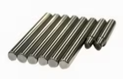
The pin does not need to contain a pre-existing cut at the boundary between plates. A shear plane identifies a section where neighboring portions are driven in different directions. It is a useful way to follow how force is transferred through continuous material.
Draw the pin as a long cylinder, then draw the plates around it. The important lines are the boundaries between differently loaded plate regions. Cutting the drawing mentally at one of those boundaries reveals a circular section of pin material resisting relative movement.
The total number of visible plates is not, by itself, a universal count of shear planes. The arrangement and the directions in which the plates transfer force determine which boundaries matter. Two neighboring plates moving together do not create the same situation as two regions pulling opposite ways.
This is why the fork-and-tongue picture is helpful. The middle member is loaded against the two outer supports. Each side of the middle member creates a corresponding force-transfer boundary through the pin.
The arithmetic counts resisting area
For a round pin, each cross-sectional area is πd²/4, where d is the diameter. A simple average shear-stress calculation divides the applied force by the total resisting area.
With one shear plane, the area is A. With two equally loaded planes, the combined area is 2A. The same force divided by twice the area gives half the average shear stress.
For an illustrative force of 1,000 newtons and a 10-millimeter pin, one circular section has an area of about 78.54 square millimeters. The ideal average is approximately 12.73 newtons per square millimeter in single shear, or 6.37 in equally shared double shear. These figures explain the geometry; they are not load ratings for a real joint.
What exactly does equal load sharing mean?
In the ideal symmetric double-shear picture, a total force F acting through the middle member is balanced by two equal opposing reactions, each F/2. Each pin section therefore carries half the total force over the same circular area A.
Writing the average stress as F divided by 2A gives the same result as writing (F/2) divided by A. One version counts the combined resisting area; the other follows the force in each section. They agree because the assumptions are the same.
If the two reactions are unequal, each section has its own average force divided by area. An illustrative split of 60 percent and 40 percent of the total force would put more average shear stress into the first section than the second. Dividing the full load evenly would conceal that difference.
This is the meaning of the word ideal in the factor-of-two comparison. It is not a vague warning. It identifies the symmetry and equal sharing that allow the simplified arithmetic to work.
The pin’s material has the same local strength characteristics before and after the connection is rearranged. What changes is how much of that material participates at separate boundaries and how the external load reaches those regions.
Could a larger pin provide the same ideal resisting area?
For a round section, area is proportional to diameter squared. A single-shear pin would need a diameter larger by √2, approximately 1.414, to provide the same one-plane area as two planes through a smaller pin.
For example, the two circular shear areas of a 10 mm pin total about 157.08 mm². A single circular section with that area has a diameter of about 14.14 mm. This compares only geometric shear area, not the complete behavior of two different connections.
The larger pin changes hole size and contact geometry as well as area. The double-shear arrangement changes the supporting layout. Equal values in one simplified calculation do not make the resulting assemblies mechanically identical.
This is another reason to distinguish “more resisting area” from “better in every way.” The calculation answers a defined question about a particular force-transfer model. It does not erase the other dimensions of the joint.
Why actual connections are more interesting
The plates also press against the curved surface of the pin. That contact creates bearing stress, a different use of the word bearing from a ball-bearing assembly. The pin may bend between supports, and the plates can deform around their holes.
If the two outer plates are not positioned or loaded symmetrically, the two shear planes may not share the force equally. Clearance between holes and pin can change how contact develops. A material’s tensile test result alone does not describe all these behaviors.
The hole walls participate in the same event

Before force reaches the pin’s imagined shear sections, it passes through contact with the plate holes. The curved pin presses against portions of the hole walls. That pressure is called bearing stress in the connection context.
The word bearing here describes contact support, not the presence of rolling bearing balls or races. A simple pinned joint can develop bearing stress without containing a rolling bearing assembly.
The plate can deform locally around the hole. Material between the hole and a nearby edge can also carry force through a limited region. These are different material paths from the circular cross-section through the pin.
Consequently, doubling the ideal shear area of the pin does not automatically double the strength of a plate that was already the limiting part. An assembly is a connected path of forces, and changing one part of that path may leave another part unchanged.
Jiyuan’s carbon and alloy round bars provide a material form from which pins and other turned components can be produced. The round section is a useful starting geometry, while the finished connection’s behavior comes from both the material and the surrounding design.
Why support spacing can introduce bending
Imagine the pin supported at two separated regions while the middle member pushes between them. The pin can behave partly like a short beam, bending between contacts while also transferring shear. Where the contacts act along the pin influences that bending.
A gap between members can change the distance between force-transfer regions. It does not add more steel area to the pin, but it changes the geometry of the loading. This is a different effect from the diameter-squared area relationship.
The ideal shear calculation deliberately isolates one part of the behavior. It is valuable because it shows clearly why two loaded sections can share a force. The surrounding picture explains why real pins are not understood through that one calculation alone.
The phrase double shear therefore identifies an arrangement: the force crosses two relevant pin sections rather than one. Under symmetric sharing, each carries half the total load. The steel has not acquired a new grade or hardness; the connection has given the load two paths across it.
One Pin, Two Shear Planes
Does double shear make the steel itself twice as strong?
No. It changes the connection geometry by providing two sections across which load can be shared. In an ideal symmetric arrangement, each plane carries half the total load. The steel’s material properties have not doubled, and unequal load sharing can change the local stresses.
Can a double-shear connection fail somewhere other than the pin sections?
Yes. The pin can bend, contact around the holes can deform, and the surrounding plates can fail. Counting shear planes addresses one part of the force path. It is not a complete rating of the joint or proof that pin shear controls its behavior.
If your inquiry concerns pin-making stock, you can share the required grade, diameter, and supplied length with Jiyuan, together with a short description of the intended machining. Those details identify the material being discussed without confusing a raw-bar description with a load rating for the completed joint.