Why Do Cast Steel Billets Have Lines Across Their Surface?
Table of Contents
Continuous casting mold oscillation can leave repeating marks as the strand’s outer shell forms and moves through the mold.
Regular lines across a continuously cast steel billet can come from the repeated motion of the casting mold. The mold oscillates while a newly forming steel shell moves through it. The shell can retain a repeating surface pattern associated with that motion, known as oscillation marks. The lines are a record of how the surface formed, rather than marks scratched onto a fully cold bar afterward.
A continuous casting mold is not a closed box holding a batch of steel until it freezes. Liquid steel enters, a shell develops against the cooled walls, and the strand keeps moving out. The mold shapes the beginning of a product that is continually leaving it.
The mold moves too
The moving steel shell is in close contact with the mold region. Sticking would disrupt its smooth passage, so the process includes mold oscillation and lubrication. The mold’s repeated movement changes the interaction near the point where the first shell forms.
The Colorado School of Mines Continuous Casting Center explains the mold region as a crucial early stage in shell formation. The surface is being created in a narrow zone where liquid steel, solidifying steel, lubrication, and a cooled moving wall all interact.
Think of drawing a long line while making a small repeated hand movement. As your hand travels down the page, the repeated motion becomes a series of features distributed along the line. In casting, the interaction is thermal and mechanical, but the link between repetition in time and spacing along a moving object is similarly useful.
The shell is being made while it moves
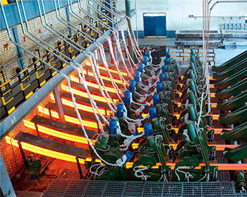
The steel does not enter the mold as a cold bar waiting to have lines embossed on it. Liquid metal enters, heat leaves through the mold region, and a thin solid shell begins to form. The place where liquid, growing solid, and the mold environment meet is changing throughout the motion.
That distinction explains why a mold with apparently smooth walls can still be associated with surface marks. The mark is not necessarily the impression of a matching groove machined into the mold wall. It can arise from the changing conditions under which the shell grows and interacts with the interface.
Research by Sengupta and Thomas on oscillation marks and subsurface hooks shows how local solidification and fluid movement interact during an oscillation cycle. Their detailed mechanism concerns the ultra-low-carbon slab conditions studied, so it should not be treated as one universal explanation of every mark on every billet. The relevant broader point is that mark formation occurs at a moving, solidifying interface.
A repeating machine motion and a changing shell can therefore produce a repeating pattern without a toothed stamping tool. The material carries the pattern away from the region where it first formed.
Time becomes distance
Suppose an imaginary strand advances 20 millimeters during each complete mold cycle. A repeating feature associated with those cycles would appear at roughly 20-millimeter intervals. If the strand advanced only 10 millimeters per cycle, the repeating pattern would be closer together.
Those numbers are an illustration, not casting settings. The underlying relationship is distance equals speed multiplied by time. A regular rhythm in the machine can become regular spacing on the material that passes through it.
This is also why a pattern can change along a length of cast steel. If the relationship between travel speed and oscillation changes, the spacing can change. The surface is preserving a trace of a process that happened over time.
Cycle spacing is different from how far the mold moves
The mold’s stroke describes the distance between positions in its up-and-down movement. Mark pitch describes the distance between successive repeating features along the strand. These are two different distances, associated with different motions.
Imagine a hypothetical mold moving up and down over a 6 mm stroke while the strand travels 20 mm during each cycle. A pattern associated with one event per cycle would have a characteristic spacing near 20 mm, not automatically 6 mm. The stroke affects the motion at the interface, but the strand’s travel during the cycle determines how far one cycle’s event is carried from the next.
The same distinction appears in a moving conveyor passing a flashing lamp. The distance the lamp moves, if it moves at all, is different from the spacing of illuminated positions on the conveyor. The timing of the flashes and the belt speed determine that spacing.
For another illustrative calculation, suppose a strand travels at 20 mm per second and a cycle lasts half a second. It travels 10 mm during the cycle. If the cycle lasts a full second at the same strand speed, it travels 20 mm. These numbers explain the relationship rather than suggesting casting settings.
The equation can be written as pitch = strand speed × cycle time. If frequency is used instead, frequency means cycles per unit time, so pitch = strand speed ÷ frequency. The units have to agree: millimeters per second pairs naturally with cycles per second, not with an unconverted cycles-per-minute number.
Count the spaces, not only the lines
A photograph or sketch can create a small counting trap. Ten lines contain nine intervals between the first and last line. If the first and tenth lines are 180 mm apart, their average spacing is 180 ÷ 9, or 20 mm.
Dividing by ten would give 18 mm and incorrectly include a tenth interval that is not present inside the measured span. The same issue occurs when counting fence posts: the spaces between posts are one fewer than the posts when measuring from the first to the last.
Averages can also hide variation. A series with alternating shorter and longer gaps can have the same average pitch as a uniformly spaced series. A single number describes the overall rhythm but not every local event.
The pattern may also be interrupted by scale, lighting, or another surface feature. A missing visible line is not automatic proof that the machine skipped a cycle. The feature might be faint or concealed. Reading a surface pattern involves separating the object’s geometry from how clearly that geometry is visible.
A line is not automatically a crack
An oscillation mark is a surface depression or pattern. A crack is a separation within the material. Both can look like lines in a photograph, especially on a dark, scaled surface, but they are different physical features.
A shallow groove can exist without a crack beneath it. Conversely, a crack may occur near a surface feature, so recognizing a regular pattern does not prove that everything below it is intact. The useful distinction is between the shape of the surface and continuity of the metal.
Lighting can exaggerate the confusion. A low light angle makes a shallow depression cast a dark shadow. Scale can also break along a line and make it look wider. A photograph records reflected light, not a cross-section through the steel.
Why the pattern can change along one billet
A billet’s length represents material formed at different moments. If the strand speed or oscillation rhythm changes, the relation between time and distance changes too. Local disturbances at the forming interface can add another variation without changing the basic fact that the mold oscillates.
For this reason, a surface is more like a record of a process than a wallpaper pattern printed from a perfectly fixed template. A regularly spaced region and an irregular region may belong to different moments in the same material’s history.
The direction of the pattern is informative too. Oscillation marks are commonly described as transverse features because they run across the direction of strand travel. A long line running along the billet belongs to a different geometric description and should not be assigned the same origin merely because it is also called a line.
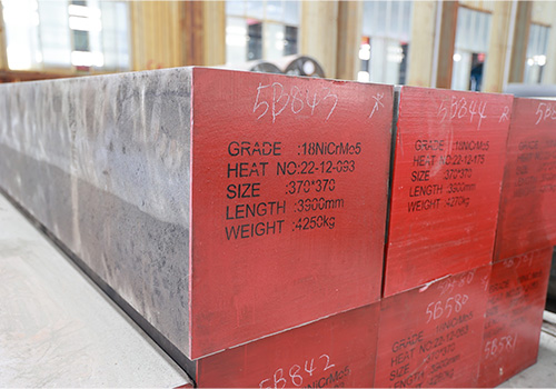
Jiyuan’s steel billet page covers cast forms that go on to further processing. If a repeating pattern on such material has prompted an inquiry, the billet’s cross-section and intended next process help explain which surface is being discussed.
Later rolling stretches and changes the original cast geometry, so the spacing on a finished product should not simply be read as the original caster pitch. Before that reshaping, the billet surface is closest to the moment when repeated motion became a sequence of marks on moving steel.
What Billet Surface Lines Can Tell You
Is the spacing of oscillation marks the same as mold travel distance?
No. Mark spacing along the strand relates to how far the strand advances during a cycle. Mold travel describes the mold’s motion. In a simplified steady case, strand speed multiplied by cycle time gives the distance between successive cycle-related marks.
Does an oscillation mark automatically mean the billet is cracked?
No. An oscillation mark is a surface feature associated with formation of the shell during mold motion. A crack is a separation in the material. They may need to be examined together, but a repeating line by itself does not establish a crack.
You can share those details with Jiyuan together with an overall view and a close view that includes a length reference. Showing both scale and direction preserves the information that a tightly cropped photograph often removes.